Design and build a wired and or wireless network connecting at least two processors.
A short read up on Inter-integrated Circuit I2C and installing additional library in Arduino would be useful
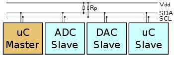
What is I2C? It is a serial protocol for two-wire interface invention by Philips. Used to connect low-speed devices like microcontrollers, I/O interfaces and other similar peripherals in embedded systems.
I2C only required two wires for communication between 2 microprocesor and can support up to 1008 slave devices and can allow more than one master to communicate with all devices on the bus.
I2C Architect
Instructions on how to install additional library into arduino can be found here. Additional library like TinyWireM.h and TinyWireS.h to arduino can be found here.
It is important to note that the I2C master library (TinyWireM) is set to run at 1MHz by default on the Attiny master chip. No changes are necessary for the I2C slave library (TinyWireS) on the Attiny slave chip as they are set at 8MHz by default.
The range of address that can be used on the Attiny45 Slave will be found here
Generally the address range from 0x08 to 0x77 can be used.
Programming the Attiny
I bootloaded my master Attiny85 at 1MHz internal clock and slave Attiny45 at 8MHz internal clock. My Master program is just a simple 2 button program and slave is just a simle blink program.
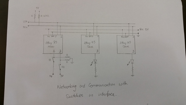
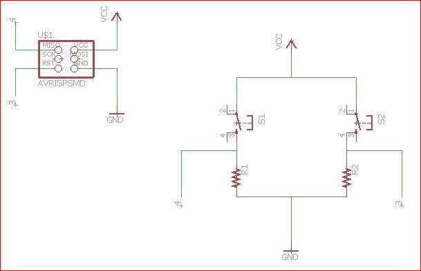
I decided to use I2C networking method to communicate between an Attiny85 as master and 2 Attiny45 as slaves because of simplicity in setup.
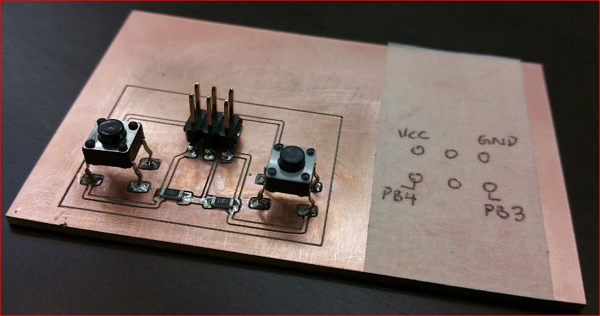
Two switches will be used to individually call out its own slave chip to run its program through the master chip.
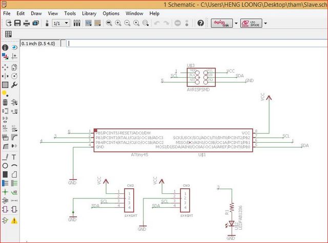
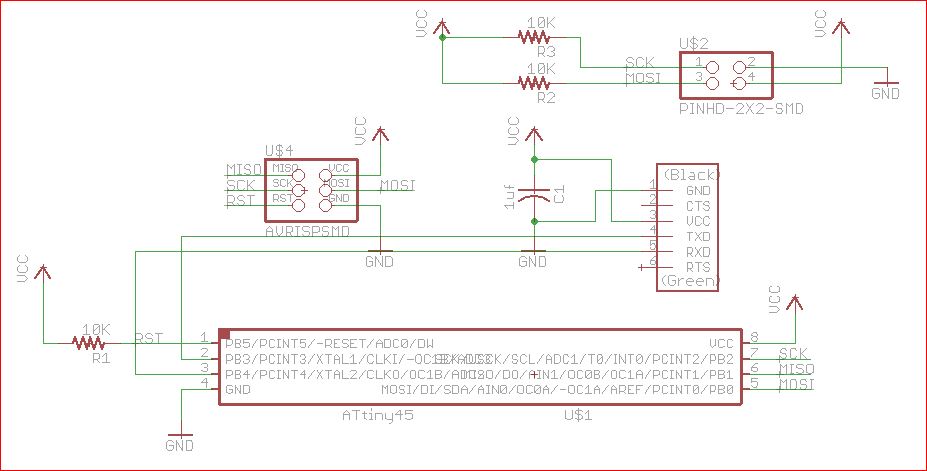
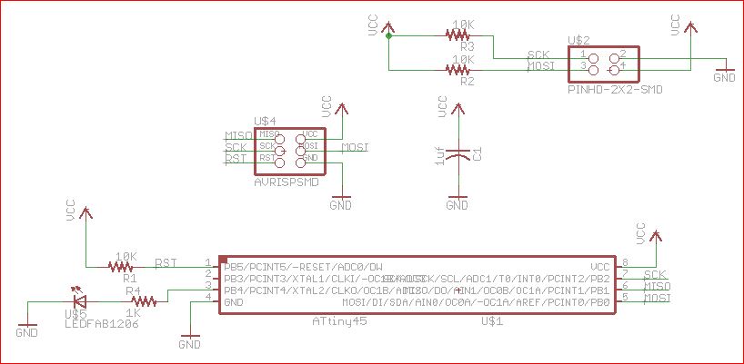
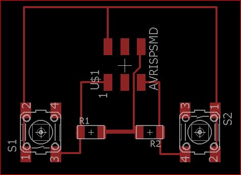
A sketch of the circuit below will illustrated how I2C connects the chip sets.
Master with push button sketch
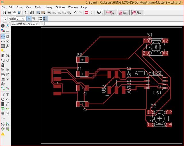
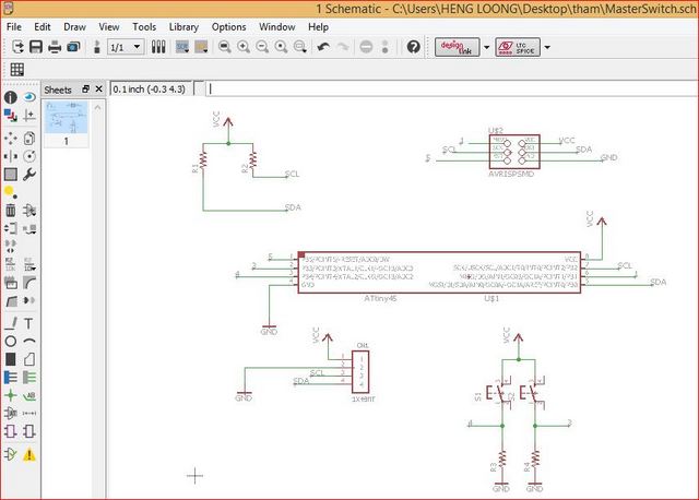
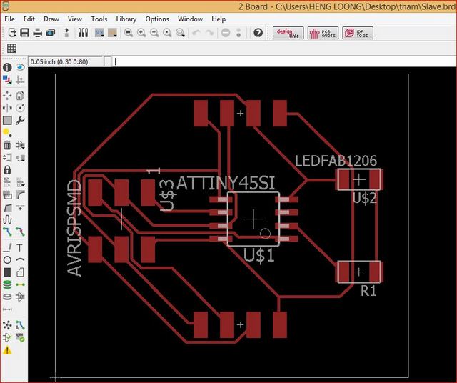
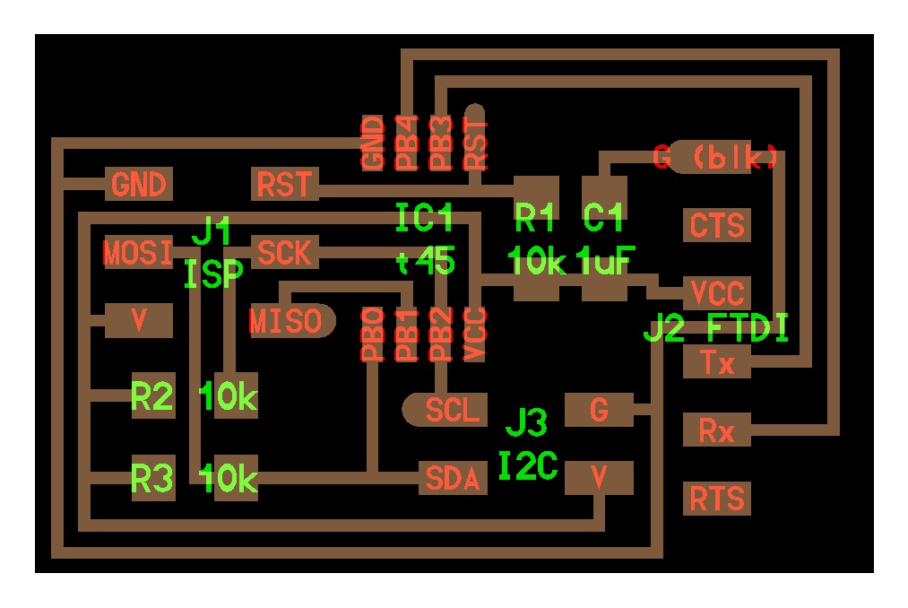
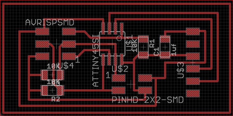
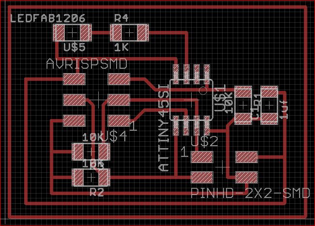
From paper to PCB
The circuit was created through EagleCAD. The process were same as in Week 6 and will not be repeated here. The process of loading of programs into the attiny chipsets will also not be repeated here.
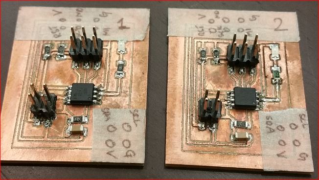
The idea was to have an Attiny85 to be Master with two micro switches mounted on the pcb and two but similiar Attiny45 Slave pcb. The two slave pcb will have the same layout design and program.
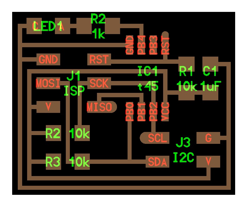
Both the slave attiny45 chip will have a simple blink program loaded and a LED connected to a output pin. Once one of the slave chip is called out it will run the blink program.
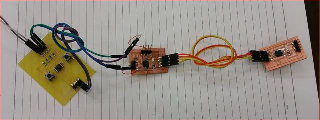
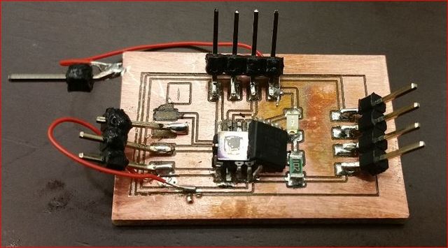
As usual, the pcb stuffs always never ever worked on my hands. I hooked up the circuit and almost expected the circuitry to failed after I had soldered the components onto the pcb. True enough, it didnt worked. Hence the fustrating process of troubleshooting begins.
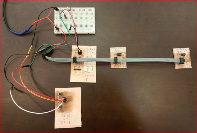
Master with 2 slaves connection
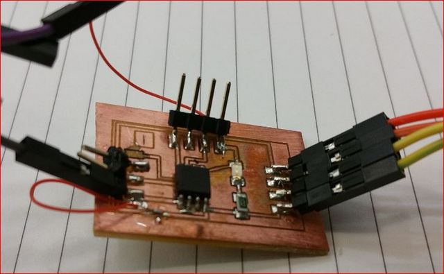
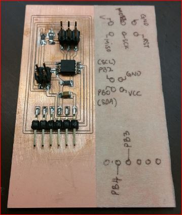
Initial diagnostic showed the slave 1 pcb board is giving problem. The copper path that connects two sets of points were open circuit. Therefore, connect these two sets of points using a thin wire. However the problem still persisted. Unfortunately, in the process of troubleshooting one of the pin terminal broke off from the board along with the copper pad.
Slave board having connectivity issues, noted the red wires
Copper pads came off during troubleshooting
From this point I stop the pcb milling process and took stock on what to do next.
Follow up on making the PCB for I2C Master PCB and Slave PCB (Update)
My colleague, Siew Chin help me by dicussing the steps in milling the PCB. We used Neil I2C for reference.
Basically, it is using 2 buttons from the "Master" to call their respective "Slaves".
"Slave 1" will blink at a faster rate because I Bootloader it at 1Mhz while "Slave 2" will blink at slower rate because it was Bootloader at 8 Mhz. Hello I2C Bridge. Click here to visit webpage.
The mistake I made here was I forgot to factor in the external power supply for the SCA and SCL communication wires in the EagleCAD. Thus had to setup an external power 5V supply with 2 x 4.7K for the SCA and SCL coms line as shown above on the breadboard.
A video of the working I2C networking and communication.
Next course of action
Since I am having issues with the pcb milling, I tried hooking up the circuit using the bread board based on the sketch above. It was a success and it worked according to what it was designed to perform. The link below showed how the micro switch called their respective slave to run their program via the master Attiny85.
What if Bluetooth is used to replace the micro switches?
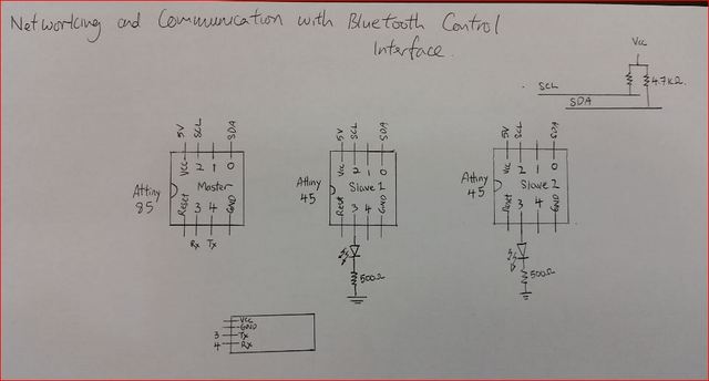
Again I started with a sketch and it is shown in the picture below.
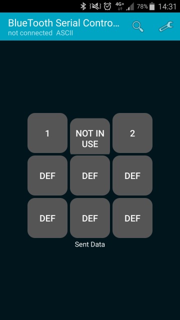
The Bluetooth device I am using is a HC-05 which I brought from Element14 and installed a BlueTooth Serial Controller app from Google Play to interface with it. Below is a screen shot of the apps being used.
One important thing to note is the TX and RX of the bluetooth device goes to pin 3 (RX) and pin 4 (TX) of the Attiny85 chip respectively.
The connection can be view on the sketch above named Master with Bluetooth sketch.
The videos below will show how the interface worked
The first video showed a simple circuit to control 1 LED using bluetooth on a arduino uno. This is for me to gain confidence.
The second video showed how Bluetooth 2 Attiny45 chips each loaded with a simple blink program. Finally the Master output to a LED after the commands were executed.
My comments
I like to mentioned that the circuits I tested with an arduino in background are not used make the circuit function. I am just using their 5 volts power because I don't a power supply and it is convenient for me to hook up the power.
I will try to incorporate WIFI into this exercise once I get an opportunity in the future. It could let me control different devices via internet remotely.